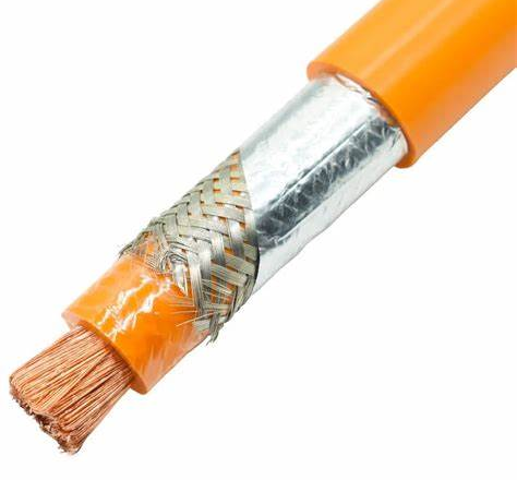
Strategie di Risoluzione di Problemi di Cable in Scenari di Applicazioni Sferenti
U metudu di posa di cable è l'ambiente di l'applicazione affettanu significativamente a difficultà di risolve i prublemi è a scelta di metudi.
Diagnosi di difetti di u cable interratu direttu: Sfide è Soluzioni
Sfida: U cable hè intarratu in terra è ùn hè micca visibile; L'umidità di a terra è e variazioni di cumpusizioni affettanu u campu elettricu è a propagazione di l'onda sonora. Pipelines adiacenti (tubi d'acqua, tubi di gas, altri cavi) pò generà signali di interferenza; L'infurmazione precisa di u caminu di u cable hè difficiule d'ottene.
Prucedure cunsigliatu:
Jugement préliminaire: Megohmmeter è multimeter sò usati per ghjudicà u tipu di difettu (cortu circuitu, circuitu apertu, colpa a terra, ecc.).
A cunferma di a strada: Aduprate un tracciatore di rotta di cable per seguità accuratamente è marcà a direzzione di u cable per evità deviazioni in u posizionamentu sussegwenti.
Pre-location: Selezziunà u metudu apprupriatu basatu annantu à u tipu di difettu.
Cortu circuitu / circuitu apertu à bassa impedenza: TDR hè preferitu.
Fallu di terra à alta impedenza: U Metudu Impulsu Secundariu (SI/ME) hè preferitu. Se u dispusitivu ùn sustene micca, pudete pruvà u metudu High Voltage Bridge (chì deve esse brusgiatu u puntu di difettu prima) o u metudu acustomagneticu dopu un impulsu d'alta tensione.
Situazione di u puntu di difettu (Pin-pointing): Posizionamentu precisu utilizendu u metudu di timing sincronu acustomagneticu in l'area indicata da i risultati di pre-situazione. Una alta tensione pulsata hè appiicata à u cable, è u sonu più forte hè situatu à sente u sonu di scaricamentu in terra. Per i difetti di terra chì ùn pruducenu micca un sonu di scaricamentu chjaru, u mètudu voltage step pò esse pruvatu.
Verificazione: Dopu chì u puntu di difettu suspettatu hè determinatu, una piccula zona pò esse scavata, o verification lucale acoustomagnetic e voltage mètudu pò esse realizatu di novu.
Affrontendu e sfide: Riduce l'errori di rotta attraversu tracciatori di rotta di alta qualità; Sceglite un ricevitore acustomagneticu cù una forte capacità anti-interferenza; Aghjustate l'energia d'impattu à alta pressione secondu e cundizioni di a terra; Una cumminazzioni di metudi corroborate i risultati cù l'altri.
Cable aereo isolatu (ABC) Risoluzione di prublemi: Cunsiglii di Locazione Rapida
Sfida: I punti di difettu sò spessu visibili, ma sò largamente distribuiti è implicanu u travagliu in altitudine alta, chì pò esse periculosu per uperà.
I difetti tipici: A strata isolante invechja è cracking, graffi di ramu, fulmini, danni d'uccelli è animali, prublemi di prucessu cumuni.
Prucessu di prova:
Ispezione visuale: Inspeccione cù cura a linea, usendu un telescopiu, per circà tracce evidenti di carbonizazione, segni di bruciatura, crepe, sovrapposizione di corpi stranieri, è altre tracce evidenti di a capa d'insulation. I camion di bucket o droni aumentanu l'efficienza è a sicurità.
Thermal Imaging: Camere termali sò aduprate per detectà l'aumentu anormali di a temperatura in u corpu di u cable, in particulare à i giunti è i terminali, quandu u cable hè operatu sottu carica. L'aumentu di a temperatura hè un signu impurtante di fallimentu precoce o sovraccarica.
Misurazione elettrica di basa: Dopu à una mancanza di energia, Aduprate un megohmmeter è un multimetru per pruvà a resistenza d'insulazione è a continuità per determinà u tipu di difettu.
Situazione di difettu: Mentre l'ispezione visuale pò revelà u puntu di difettu, TDR o acustomagneticu (se l'impulsu d'alta tensione pò esse applicatu) pò ancu esse usatu per localizà u puntu di difettu s'ellu ùn hè micca evidenti (P.e., rottura interna).
Cumpetenze: Aduprate carte di rotta è indicazione geografica per aiutà à u pusizziunamentu; Prestate attenzione à l'influenza di i fatturi climatichi nantu à a termografia infrared è l'ispezione visuale.

Diagnosi di difetti di cable in Tunnels/Cable Trenches: Impattu Ambientale è Metodi di Rilevazione
Sfida: L'ambiente hè chjusu, è ci pò esse risichi cum'è gasi dannusu, carenza di ossigenu, alta temperatura, è alta umidità; U spaziu hè strettu, è l'equipaggiu hè sconveniente per portà è operate; Ci sò parechji cables, è hè difficiule di identificà u cable di destinazione; U rumore ambientale pò interferisce cù a rilevazione acustica.
Prucedure cunsigliatu:
Valutazione di Sicurezza: A rilevazione di gas è a ventilazione deve esse realizatu prima di l'ingressu per assicurà a sicurità.
Identificazione di destinazione: Cunfirmà i cavi difettosi utilizendu tag d'identificazione di cavi è disegni di u sistema.
Ispezione visuale: Inspeccione cù cura longu u caminu di u cable, in particulare à i articuli è i supporti, per i segni di danni à l'insulazione, ablazione, deformazione, ecc.
L'imaghjini termali infrarossi: Cunduce durante a carica, per detectà i punti caldi anormali.
Pre-location: TDR (per bassa resistenza / circuitu apertu) o Metudu Dual Pulse (per alta resistenza).
Situazione di u puntu di difettu: U posizionamentu sincronu acustomagneticu in tunnelli / trinchee hè generalmente più faciule ch'è l'enterramentu direttu perchè a propagazione di u sonu di scaricamentu hè più diretta.. Aduprate un sensor acusticu di cuntattu (pusatu nantu à a superficia di u cable) o un sensore accoppiatu à l'aria in cumbinazione cù un sensoru di campu magneticu.
Scaricamentu Parziale (PD) Detezzione: Tunnels / trinches sò un ambiente favurevule per a rilevazione di scarica parziale, è u rumore di fondo hè relativamente stabile. L'ispezioni PD in linea o offline ponu esse realizate cù sensori TEV (su supporti metallici o vassoi), sensori HFCT (nantu à i fili di messa a terra), o sensori ultrasonici (nantu à a superficia di u corpu di cable o accessori) per detectà i primi difetti di l'insulazione.
Diagnosi di difetti di u cable sottumarinu: Requisiti Speciali è Tecnulugia
Sfida: L'ambiente hè estremu, esige un equipamentu prufessiunale impermeabile è resistente à a pressione; Hè necessaria una alta precisione di posizionamentu perchè u costu di riparazione hè estremamente altu; U travagliu di riparazione hè complicatu.
I difetti tipici: Ganci di ancora, graffi di rete di pesca, danni à l'ancora di a nave, terrimotu è tsunami, l'arburu internu di l'acqua / l'arburu elettricu.
Prucedure cunsigliatu:
Pre-location: Si basa principalmente nantu à l'equipaggiu TDR specificu per i sottumarini d'alta precisione, chì generalmente richiede l'usu di boe o misurazione di a pusizione di a superficia assistita da GPS. U metudu di ponte d'alta tensione pò ancu esse usatu, s'è pussibule.
Situazione precisa è rilevazione: Estremamente difficiule. A ricerca dettagliata pò esse dumandata in cunjunzione cù sonars, robots sottumarini dotati di sensori acustomagnetici, o sensori di flussu chì rilevanu cambiamenti in u campu magneticu causati da correnti di fuga.
Riparazione di difetti: E navi prufessiunali di posa di cavi sottumarini è di riparazione sò spessu richieste, è a riparazione hè fatta cù a tecnulugia di cunghjunzione umida o secca, chì hè costu.
Equipamentu speciale: Sonda TDR sottumarina, ricevitore sincronu acustomagneticu subacqueu, ROV (Veiculu operatu à distanza).
Cable di cumunicazione (Fibra / Copper) Risoluzione di prublemi: OTDR è altri strumenti
U diagnosticu di difetti di u cable di cumunicazione hè diversu da i cavi d'alimentazione, in particulare i cavi di fibra ottica.
Guasto di u cable di fibra ottica:
I difetti tipici: Fibre rotte, connettori sporchi/dannati, perdita eccessiva di splice, raggiu di curvatura eccessivu (macrobend/microbend).
Strumenta basica: Reflectometru otticu di u duminiu di u tempu (OTDR).
Principiu: Simile à TDR, l'OTDR trasmette impulsi luminosi in a fibra è analizà i segnali di riflessione Rayleigh è Fresnel longu u percorsu di a fibra.. Analizendu a forma è a pusizione di a curva di riflessione / scattering, hè pussibule di determinà a durata, attenuazione, perdita di splice, perdita di cunnessu, è u locu di u puntu di rottura di fibre.
Applicazioni: Misurà accuratamente a distribuzione di perdita di ligami di fibra, individuare le pause, punti di alta perdita, cunnessu, o prublemi di splice.
Altri Strumenti:
Fonte di luce è misuratore di putenza: Adupratu per misurà a perdita generale di u ligame otticu è stabilisce s'ellu ci hè un prublema.
Localizzatore visuale di difetti (VFL): Brilla una luce rossa visibile per detectà rotture di fibre, curve, o prublemi di cunnessu nantu à distanze brevi (a giacca di fibra deve esse otticamente non densa).
Microscope à fibre: Inspecciona l'estremità di i connettori per a pulizia, graffi, o danni.
Guasto di cable di cobre:
I difetti tipici: Circuitu apertu, cortu circuitu, cablaggio sbagliatu, circuitu apertu, diafonia, perdita eccessiva di ritornu.
Strumenti basi: Certificatu di cable / Tester o TDR (per i circuiti aperti, cortu circuiti).
Applicazioni: Misura a lunghezza di a coppia, schema di cablaggio (per determinà i cortu circuiti, apre, mis-fili, coppie incruciate), Near-End Crosstalk (NEXT), Crosstalk à l'extrême (FEXT), perdita di ritornu, perdita d'inserzione, è altri paràmetri per valutà u funziunamentu di u ramu è localizà i difetti. A funzione TDR hè spessu usata per indicà punti di circuitu apertu o di cortu.
Analisi approfondita di i casi tipici di difetti di cavi
Cumminendu a teoria è a pratica hè a chjave per maestru di a tecnulugia. Eccu alcuni casi tipici di diagnostichi di difetti di cable in diverse scenarii.
Casu 1: Guasto di terra monofase di un cable d'alimentazione d'alta tensione in una pianta chimica
Sfondate: In l'area di una grande pianta chimica, un alarme di guasto à terra monofase hè accadutu nantu à l'alimentatore in uscita di a 35Cavu d'alimentazione insulatu kV XLPE in funziunamentu, pruvucannu una mancanza di energia in l'area affettata.
Fenomenu di colpa: U dispusitivu di prutezzione di a terra di u sistema operatu, è l'interruttore di circuitu s'hè lampatu. L'operatore hà pruvatu à ricuperà, ma u relé hà operatu di novu.
Passi di Diagnosticu è Prucedure:
Jugement préliminaire
Dopu à l'interruzione di energia, Aduprate un megohmmeter 2500V per pruvà a resistenza d'insulazione di u cable difettu. A resistenza d'insulazione di e fasi A è B hè normale (> 2000 MΩ), è a resistenza d'insulazione trà a fase C è a terra diminuite significativamente, à solu 5 MΩ. Il s'agit d'un défaut à la terre à la phase C, è a resistenza à u puntu di difettu hè resistenza mediu-altu.
Pre-location
Perchè hè un difettu di alta impedenza, aduprendu TDR cunvinziunali direttamente pò esse micca efficace. U squadra operatore hà decisu di utilizà Ultra-Low Frequency AC Hipot (VLF) prova cù perdita dielettrica (Allora Delta) e Scarico Parziale (PD) rilevazione per pre-location è per valutà a cundizione di u cable à u stessu tempu. Cunnette u tester VLF trà a fase C è a terra, è applica 0.1 Hz, 2U0 (circa 40 kV) tensione AC. Durante a prova, si trova chì u valore tanδ di a fase C aumentava rapidamente cù a tensione crescente, è un signalu di scaricamentu parziale di grande amplitude cuntinuu hè statu rilevatu. Analizendu e caratteristiche di propagazione di u signale (cum'è u posizionamentu di a differenza di tempu), u puntu di difettu hè stimatu à esse situatu circa 1.2 km da a substazione.
Posizionamentu Precisu (Metudu di l'Impulsu Quadraticu)
Per pre-localizà più accuratamente per a puntuale successiva, l'O&A squadra M hà utilizatu un tester di difetti di cable cù una funzione d'impulsu quadraticu. Cunnette u generatore di impulsi di alta tensione (stabilitu à 15 kV) à a fase C è a terra, è mette u tester di cable à u modu di impulsu secundariu. Dopu applicà un impulsu d'alta tensione, un flashover accade à u puntu di difettu, è u tester di cable cattura una forma d'onda di riflessione d'arcu chjaru. A forma d'onda hè stata analizata, è a distanza di difettu hè stata calculata per esse 1.22 km. I risultati di i dui pre-locations eranu fundamentalmente cunsistenti.
Rilevazione di punti di difettu (Metudu acustomagneticu)
Sicondu u risultatu di pre-location di 1.22 km, O&U persunale M hà purtatu u ricevitore sincronu acustomagneticu è ascoltò u sonu in terra in l'area intornu. 1.2 km lungo a direzzione indicata da u radiumetru (tracciatore di rotta). U tracciatore di u percorsu di u cable hà cunfirmatu prima a direzzione precisa di u cable in terra. L'operatore hà ascoltatu attentamente a terra mentre applicà un impulsu di alta tensione di 15kV, è infine intesu u sonu di scaricamentu più forte à una distanza di 1225 metri da a fine di a prova. Cumminatu cù u ghjudiziu sincronu di u signale di u campu magneticu, u locu precisu di u puntu di difettu hè statu determinatu.
Scavi è Verificazione
Una piccula zona di scavi hè stata fatta in u locu determinatu da u metudu acustomagneticu, è s'hè trovu chì u cable avia una articulazione cù tracce negru nantu à l'insulazione esterna. A dissezione di l'articulazione hà revelatu chì u riempimentu internu (P.e., grassu di silicone) avia fallutu, è l'intrusione di l'umidità avia purtatu à a deteriorazione di l'umidità di l'insulation, furmendu l'arburi elettrici, chì eventualmente si rompe è scaricatu à alta tensione. U puntu di difettu era esattamente u listessu cum'è u risultatu di diagnosticu.
Soluzione: Sustituite l'articulazione difettu è verificate l'altri articuli di u stessu batch, eseguendu a sustituzione preventiva o trattamentu di periculu oculatu.
Casu 2: Riparazione rapida di l'errore di fibra di u cable di cumunicazione in un centru di dati
Sfondate: Un grande centru di dati hà allargatu a so capacità è hà stallatu un novu batch di multimode cavi di fibra ottica. Durante u prucessu di cumissioni, s'hè trovu chì un ligame in fibra ottica chì cunnetta i dui edifici ùn pudia micca cumunicà nurmale, è a perdita di signale otticu era tamanta.
Fenomenu di colpa: Attraversu a prova di u metru di putenza otticu, si trova chì a perdita di ligame otticu era assai più altu ch'è previstu, vicinu à l'infinitu, è a fibra ottica era suspettata di esse rottu.
Passi di Diagnosticu è Prucedure:
Jugement préliminaire
E teste end-to-end sò state realizate cù una fonte di luce è un metru di putenza ottica, è hè statu cunfirmatu chì u ligame ùn era micca circuitu apertu è a perdita era summamente alta. Fibra suspettata rotta o severamente curvata.
Situazione di difettu (OTDR)
Cunnette l'OTDR à una estremità in a sala di l'equipaggiu è selezziunate a lunghezza d'onda ottica adatta (P.e., 850nm o 1300 nm, currisponde à a fibra multimode). Dopu chì l'OTDR hà emessu un impulsu luminoso, un grande piccu di riflessione Fresnel era chjaramente affissatu nantu à u graficu di a forma d'onda, seguita da nisun signalu spargugliatu o riflessu. Questu indica chì a fibra hè stata completamente rotta à quellu puntu. L'OTDR hà calculatu automaticamente chì u puntu di ruttura era situatu 356 metri da a fine di a prova.
Ricerca è Verificazione in situ
Sicondu a distanza di 356 metri, O&U persunale M cumminatu cù i disegni di cablaggio di u pipeline è u ponte per fà una ricerca. In un pozzu di pipa circa 350 metri da a presa di fibra ottica di a sala di l'equipaggiu, hè statu trovu chì a fibra ottica puderia esse struitu o curvatu durante u prucessu di filettatura di pipa, causanu a rottura di a fibra ottica. L'ispezione visuale hà ancu cunfirmatu a rottura.
Soluzione
Riparazione di splicing di fibra ottica in un pozzu di pipa. Aduprate una cleaver di fibra per tagliate l'estremità rotte, pulisce a fibra, è utilizate un splicer di fusione per allineà è salda cù precisione l'estremità. Dopu chì u splicing hè cumpletu, u ligame hè riprovatu cù un OTDR per cunfirmà chì a perdita di splice hè qualificata (di solitu < 0.1 dB) è u signale à a fine di u ligame hè normale. U ligame hà restauratu a cumunicazione.
Lezzione amparata
U locu di u puntu di rottura di a fibra hè una di l'applicazioni più classiche di OTDR, chì hè veloce è precisu. Per i cavi di cumunicazione, in più di break points, OTDR pò diagnosticà in modu efficace i difetti cum'è splices à alta perdita, prublemi di cunnessione, e macrocurvature.
Casu 3: Diagnosi cumpleta di difetti d'alta resistenza in i cavi di media tensione in i parchi industriali
Sfondate: Unità principale in anellu 10 kV (RMU) cable in uscita (Isolamentu XLPE) in un parcu industriale sperienze friquenti guasti à terra istantanee monofase, causandu a RMU a trip, ma a maiò parte di i reclosure sò successu. U fenomenu di colpa hè intermittente.
Fenomenu di colpa: U dispusitivu di prutezzione di u sistema opera istantaneamente, è u registru mostra chì hè una mancanza di terra monofase, ma a culpa ùn cuntinueghja, è a ricucitura hè successu. A resistenza d'insulazione di a prova di Megohmmeter hè in a gamma normale, ma a rottura si verifica quandu si esegue a prova di tensione di resistenza VLF.
Passi di Diagnosticu è Prucedure:
Jugement préliminaire
Istantaneu, fallimentu intermittenti è test di megaohmmetru normale, L'altu suspettu hè un difettu d'impedenza alta o un difettu di flashover, chì pò esse ligata à u livellu di tensione è i cambiamenti ambientali. Megohmmeters ùn sò micca capaci di detectà tali difetti.
Valutazione di l'insulazione (VLF + Allora Delta + PD)
A 0.1 Hz, 1.5 U test d'aumentu di tensione U0 hè realizatu nantu à u cable cù l'equipaggiu di prova di tensione di resistenza VLF (più bassu di u valore di tensione di resistenza standard per evità di brusgià u puntu di difettu). In u prucessu di rinfurzà a tensione, si trova chì a perdita dielettrica valore tanδ aumenta significativamente è non-linearly cù a tensione crescente, è un segnu cuntinuu di scaricamentu parziale appare quandu una certa tensione hè ghjunta. Analizà e caratteristiche di u signale PD per determinà s'ellu ci hè u difettu in u corpu di u cable o in una articulazione. A funzione di locu indica chì u difettu hè apprussimatamente à una certa distanza in l'area di u cable.
Posizionamentu Precisu (Metudu di l'Impulsu Quadraticu + Metudu acustomagneticu)
Per pre-localizà è precisamente situà, hè necessariu “eccitare” u puntu di difettu per rende stabile durante a scaricamentu d'alta tensione o a rottura. Cunnette u cable à u furgone di prova di difetti di cable (chì cuntene u generatore d'impulsu d'alta tensione è l'unità principale di impulsu secundariu). Primu, pruvate à pre-localizà cù u metudu d'impulsu quadraticu, stabilisce a tensione per esse vicinu à a tensione operativa di punta (P.e., 15kV). Dopu parechji impulsi (colpi), una stima di distanza (P.e., 750 metri) hè ottenuta. Allora, A pinpointing acustomagneticu hè realizatu nantu à u caminu di u cable intornu 750 metri. Hè stata applicata una alta tensione pulsata, u sonu di a terra hè stata attentamente intesu, u signale di u campu magneticu hè statu osservatu, è infine, u sonu di scaricamentu più forte era intesu à una distanza di 755 metri da a fine di a prova.
Scavi è Verificazione
L'escavazione in questu puntu hà revelatu chì u cable era situatu in una trinchera sotterranea cù una articulazione prefabbricata in questu locu.. Inspeccione l'aspettu di l'articulazione è truvate chì a cinta di stampa hè stata ligeramente danatu, è l'intrusione di l'umidità era suspettata. Dopu dissecting l'articulazione, Piccole tracce di scarica elettrica sò state trovate à l'interfaccia trà u conu di stress d'insulazione è a capa d'insulazione di u corpu di cable., chì pruvò chì u difettu quì era a causa di u difettu intermittente di flashover d'alta resistenza.
Soluzione
Sustituite u connettore difettu (cunghjunta). Siccomu u connector hè prefabbricatu è hà una longa vita di serviziu, l'altri ghjunti nantu à a listessa sezione di cable sò pruvati per a prova preventiva (P.e., prova di scarica parziale ultrasonica o TEV) per valutà a so cundizione.
Lezzione amparata
Per i difetti intermittenti di alta impedenza, I testi di basa megohmmeter sò spessu inefficaci è devenu esse cumminati cù teste di alta tensione (VLF) e tecniche di diagnostica avanzata (Metudu di impulsu quadraticu, metudu acustomagneticu) per diagnosticà è situà in modu efficace. A pacienza è l'investigazione meticulosa in situ sò critichi.
Custruì un Sistema Efficace di Prevenzione è Mantenimentu di Guasti di Cable
“A prevenzione hè megliu cà una cura”. Un mantenimentu preventivu efficace pò riduce significativamente i tassi di fallimentu di u cable, allargà a vita di u cable, riduce l'interruzioni di energia, è più bassa O&M costa.
Prughjetti Preventivi Periodichi è Programmi di Inspezione
Stabbilimentu è implementazione stretta di un prugramma d'ispezione di cable hè a basa per a prevenzione di fallimenti:
Elementi annuali / Termine:
Test di resistenza à l'insulazione: Misura regularmente per osservà a so tendenza cambiante. A diminuzione cuntinua di u valore di resistenza d'insulation hè un signalu impurtante di l'anziane di l'insulation.
Scaricamentu Parziale (PD) Surviglianza: In particulare per e linee critiche è i cavi invechjate. I primi difetti di insulazione ponu esse rilevati offline (P.e., in cumbinazione cù a tensione di resistenza VLF) o per mezu di u monitoraghju in linea.
Tan Delta Test: Di solitu realizatu in cunjunzione cù a tensione di resistenza VLF, valuta u gradu generale di umidità o invechjamentu generale di u cable.
Test di corrente di fuga di tensione di resistenza DC: Mentre VLF hè più cunsigliatu per cavi XLPE, Ci sò sempre applicazioni per a prova DC per i cavi di carta d'oliu, ecc., fucalizza nantu à u cambiamentu di a corrente di fuga cù u tempu.
Articuli trimestrali / Inspection:
Ispezione di temperatura di u cunnessu / terminazione: Aduprate una camera termale o un termometru infrarossu per verificà regularmente a temperatura di a superficia di e junzioni di cable è i capi terminali. Temperature anormalmente elevate ponu indicà una mala cunnessione, resistenza di cuntattu eccessiva, o difetti interni.
Ispezione di l'ambiente operativu: Verificate se a fossa di cable, tunnel, coperchio di tombino, sustegnu, bloccu di u focu, ecc., sò in boni cundizioni, è s'ellu ci sò prublemi cum'è l'acqua stagnante, articuli varii, gasi corrosivi, è infestazioni animali.
Ispezione di l'apparenza: Inspect è verificate se u corpu di u cable, guaina, strata di armatura, è a strata anti-corrosione anu danni, deformazione, gonfiante, è altri fenomeni anormali.
Introducendu a Tecnulugia Smart Monitoring Online
Cù u sviluppu di a tecnulugia, sistemi di surviglianza in linea intelligenti ponu furnisce infurmazioni più cuntinui è cumplessi nantu à u statu di u funziunamentu di i cavi, rializà a trasfurmazioni da mantenimentu periodicu à monitoraghju di cundizione è mantenimentu predittivu.
Sensazione di a temperatura distribuita (DTS): A distribuzione di a temperatura di l'intera linea di cable hè monitorata in tempu reale cù fibra ottica disposta vicinu à u cable. Questu hè un mezzu efficau per prevene l'invechjamentu termale è i difetti di sovraccarichi per esse capace di detectà sovraccarichi di cable., cattiva dissipazione di u calore, o l'influenza di e fonti di calore esterni in u tempu.
Scaricamentu parziale in linea (PD) Sistema di monitoraghju: HFCT, TEV, o sensori ultrasonici sò stallati à i terminali di u cable è i articuli critichi per monitorà i signali PD 24/7. Per mezu di a cullizzioni di dati, analisi, e valutazione di tendenza, I difetti di l'insulazione iniziale ponu esse truvati in u tempu.
Piattaforma di monitoraghju in linea cundizionale: Integra DTS, PD in linea, currente, tensione, temperatura, umidità, è altri dati sensori, attraversu l'analisi di big data è l'algoritmi di intelligenza artificiale, valutà in modu cumpletu è diagnosticate in modu preditivu u statu di salute di i cavi, è truvà periculi nascosti in anticipu.
Optimizing Design, Custruzzione, è Gestione di l'operazione
Stage di cuncepimentu: Selezzione raghjone di u tipu di cable è a sezione trasversale, considerazione di l'ambiente di posa, caratteristiche di carica, è capacità di cortu circuitu; Ottimisate u routing per evità e zone corrosive è e zone propensi à danni esterni; Standardizà u disignu di tunnelli di cable è canali per assicurà una bona ventilazione è dissipazione di u calore.
Fase di custruzzione: Implementa strettamente e regule di prucessu di stallazione, cavu di cuntrollu tiranu a tensione è u raghju di curvatura; Assicurà a qualità di i capi di cable è ghjunti, aduprà materiali qualificati, è assicurà un bonu sigillatu; Specificazione di u materiale di rinfurzà è a prufundità (per cavi interrati direttamente); Fate un bonu travagliu di sigillà u tubu è l'entrata di u tunnel per impediscenu l'ingressu di l'animali è l'umidità; Testi stretti di trasmissioni (P.e., Tensione di resistenza VLF + test tanδ + Test di PD) sò realizati nantu à i cavi appena posti.
Gestione di l'operazione: Evite l'operazione di sovraccarichi à longu andà di i cavi; Rafforza a gestione fiduciale di a custruzzione per prevene i danni di forza esterna; L'acqua pulita è i detriti in u canali di cable in u tempu; I dati operativi sò monitorati è analizati.
Migliurà e cumpetenze di u persunale è e capacità di risposta d'urgenza
Formazione prufessiunale: Train regularmente u cable O&U persunale M nantu à a tecnulugia di diagnostica di difetti è e prucedure operative di sicurezza per assicurà chì sò competenti in l'usu di l'equipaggiu di prova avanzatu è e capacità di analisi di difetti.
Pianu d'urgenza: Formulate un pianu d'emergenza detallatu per i fallimenti di u cable, clarificà a persona rispunsevuli, prucessu di dispusizione, è preparazione materiale per ogni ligame, è accurtà u tempu di risposta di difettu.
Strumenti: Dotatu d'equipaggiu cumpletu è affidabile di diagnostica di difetti è equipaggiu di prutezzione di sicurità.
Cunclusioni: Versu un Futuru Intelligente è Predictivu di Operazione è Mantenimentu di Cable
I difetti di u cable sò una sfida significativa chì affetta l'affidabilità di u putere, cumunicazione, è sistemi industriali. A maestria di a tecnulugia d'identificazione sistematica di difetti è di diagnosi hè a chjave per riduce e perdite è assicurà un funziunamentu sicuru.. Sta guida sorta i tipi di difetti cumuni di u cable è e cause, introduce tecnulugie è equipaghji di rilevazione cumuni è avanzati in dettaglio, è furnisce strategie pratiche di risoluzione di prublemi per diversi scenarii, cumplementatu cù casi tipici per aiutà à capiscenu.
Ùn vecu l'ora, cù l'integrazione prufonda di tecnulugia cum'è l'Internet di e Cose, grandi dati, è intelligenza artificiale, U funziunamentu di u cable è u mantenimentu acceleranu u sviluppu versu l'intelligenza è a previsione. U sistema di diagnosticu intelligente basatu nantu à i dati di monitoraghju in linea pò ottene una valutazione continua è un avvisu precoce di u statu di u cable, in modu di cambià da a riparazione di emergenza passiva à u mantenimentu attivu, maximizà u valore di l'assi di cable, è custruisce una rete di trasmissione di energia è infurmazione più affidabile è resistente.
Ricumandemu chì l'industrii pertinenti cuntinueghjanu à investisce in tecnulugia di rilevazione avanzata è sistemi di monitoraghju intelligenti, rinfurzà a furmazione di u persunale, è ottimisate continuamente e strategie di operazione è mantenimentu per affruntà l'ambiente operativu sempre più cumplessu è i crescenti esigenze di affidabilità